
(This is a follow-up on part #1)
Electrical circuits
Adapting the electrical circuits
Here are the different circuits on board, as originally designed by the shipyard:
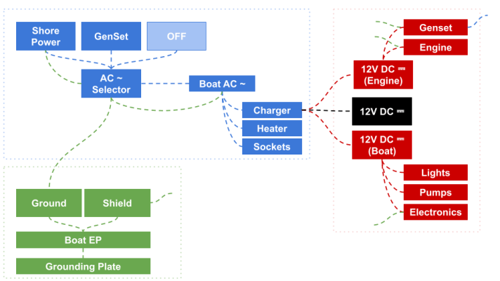
Blue: 240V AC
When connected to shore power or running the generator (same input), the boat AC circuits are powered. These AC circuits include the 12V battery charger, the water heater and various sockets on board. Each sub-circuit has a 16A limit. Shore power input also has a 16A limit (and differential breaker). When connecting to shore power, the whole grounding system is then connected to the marina’s Equipotential Plane (EP).
Green: grounding and shielding
This grounding/shielding circuit is a tree-shaped circuit connecting all grounded devices including AC sockets. “Tree-shaped” means that the circuit is not forming any loops.
Red/Black: 12 V DC
This is a floating 12V DC circuit, “floating” means that the negative is not connected to the grounding system ; this is a way to avoid stray currents and to keep the grounding/shielding system from carrying any current. In Europe (ISO 13297) this is one of the allowed design. The other design (mandatory by ABYC E-11 standards), is to interconnect the DC negative and the grounding circuit in one single point in order to avoid creating galvanic loops.
A new 48V DC circuit
When we added a new 48V DC circuit for propulsion, there was also a large impact on the AC systems: the 48V DC charger/inverter is now the entry point for shore-power and the genset, and the single device providing power to the onboard AC:
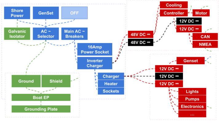
The main AC selector (shore-power, genset, off) is still being used, It feeds the 48V inverter/charger and also a direct “power socket” (in case the inverter/charger fails, we still have a direct access to AC). The 48V inverter/charger now feeds the AC circuits (water heater, sockets, 12V charger) directly from the 48V batteries (or shore power, or the genset)
The 48V DC circuit is also “floating“, and it has it’s own 12V sub-circuit (sharing the same negative) to power propulsion related circuits (CAN, NMEA, control LEDs, cooling, etc.) The propulsion electrical circuit (48V DC and 12V DC) are isolated from the other 12V DC.
Also, a galvanic isolator has been added to the shore-power input circuit: the boat EP is now isolated from the marina’s EP, but still allowing proper grounding during an active electrical fault (i.e. we are still protecting the people onboard.)
Mechanical parts
Connecting the electric motor to the saildrive (shaft)
The electric motor we selected (ENGIRO 205W 04013 SHE) has an internal spline (ANSI B 92.1, 9 tooth, 16/32 DP flat root, side fit).
On the other side, the Yanmar SD25 saildrive input shaft has a proprietary internal spline specification. I could not find any spline specs matching it anywhere. On the saildrive, the vertical drive shaft is not driven directly, the mechanical input has to pass through a torque-limiter first. The torque limiter has the same Yanmar-specific spline (internal splines on both sides.)
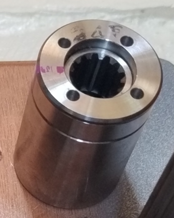
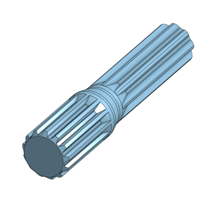
Usually, to connect motors to shafts, mechanical coupling devices are used. Those couplings are designed to absorb misalignment and shocks. I decided to ensure a proper alignment by design and to use the torque limiter as a coupling device – the torque limiter allows some play in both of its sides. To connect the motor to the torque limiter, a specific shaft (with the Yanmar-specific spline on one side and the ANSI spline on the other side) has been designed:
Aligning the motor and the saildrive (housing)
Now that we have a good idea about how mechanical movement is going to flow from the motor to the saildrive shaft, we need to tackle some more contrains:
- We need a way to hold oil for the saildrive, up to the torque limiter
- We need to ensure the motor and the saildrive shafts are perfectly aligned in all directions
- We need a material that is strong and easy to work with
- We need to ensure that the oil will stay inside and that the sea will stay outside, and that both won’t ever mix.
To build this housing, made of 3 parts, we used marine plywood, epoxy resin and fibreglass.
- The lower part (sandwiched in the hull) is 30 mm thick (2 x 15mm layers).
- The middle part (the saildrive is bolted in it, through the bottom part) is 60 mm thick (4 x 15 mm layers).
- The upper part (motor support) is 30 mm thick (2 x 15 mm layers).
- 2 layers (30 mm) of plywood have also been epoxied to the sides of the bottom part (saildrive) and the top part (motor).
The center hole on all 3 parts has been drilled in one shot and serves as a reference for all other holes (saildrive bolts, motor bolts, etc.):
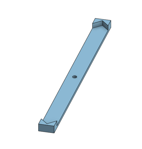
Several templates have been printed and then 3D printed at a later stage, to guide the drilling of all holes from the reference center holes:
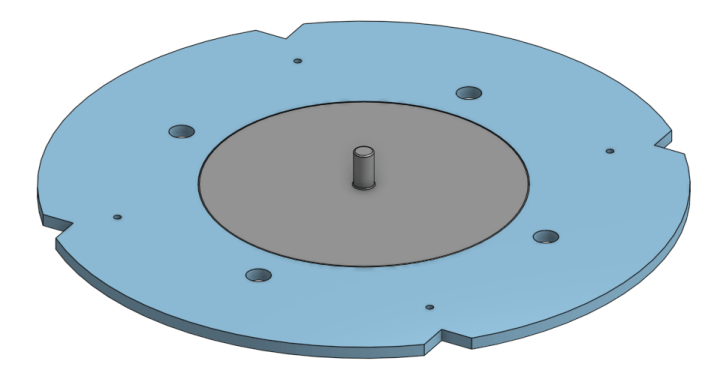
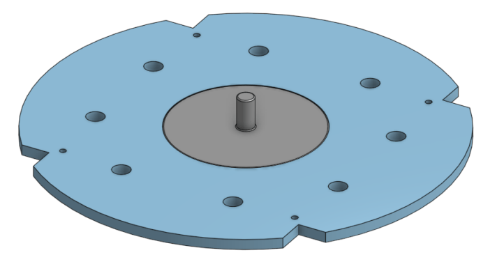
Once all marine plywood layers where drilled and cut to size, the final assembly look like this:
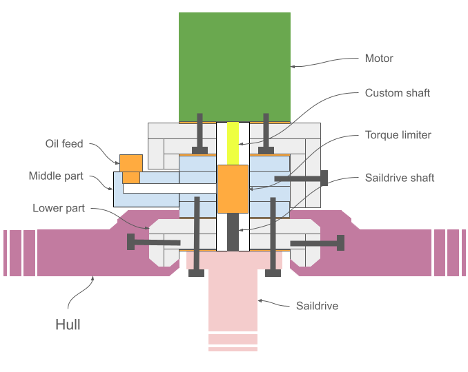
Compared to a classic saildrive that is bolted to the engine/transmission, in this installation the saildrive is fixed to the bottom part (bonded to the hull) and middle part (8 x M10 bolts and M17 stainless steel inserts.) The bottom part is firmly bonded to the hull using 8 x M8 bolts and as much layers of glass & epoxy as possible.
Other custom parts: the cooling circuit
For the cooling circuit, several parts have been designed in order to make a flat cooling surface for the electronic controller with off-the-shelf, aluminium, square tubes:
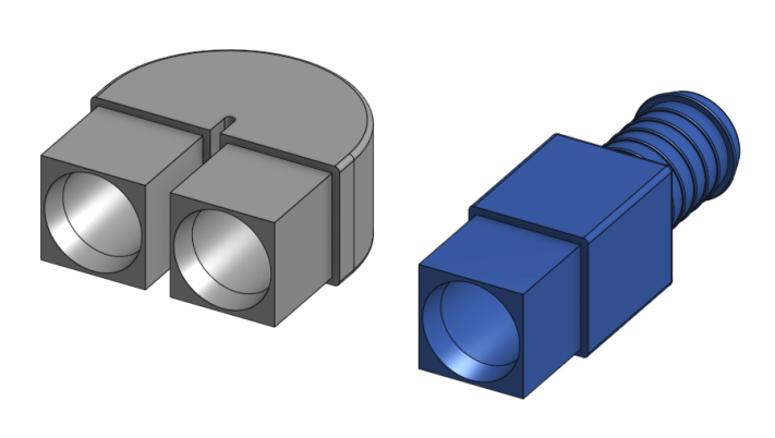
Those parts are made of nylon, reinforced with glass fibers ; the barbs are designed to accommodate ø19mm cooling hoses (same diameter than on the motor and the circulation pump).
Connecting the motor controller
On my previous electrical propulsion installation (Rim Drive POD), I noticed the lack of a proper distribution system. The motor controller (VESC Maxim 120 from VescLabs) is the brain of the system and has a 39-pin connector for I/Os. All wires going to the controller are in 1 of 3 different categories:
- Power circuit
- Control & Communications
- Low voltage distribution
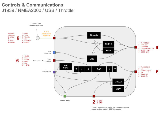
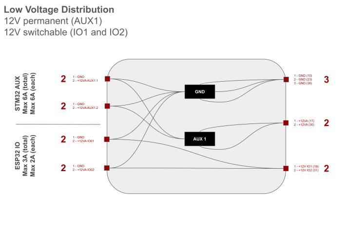
On the following diagrams, the left side is the boat side, the right side is the VESC controller side.
Power circuit (48V)
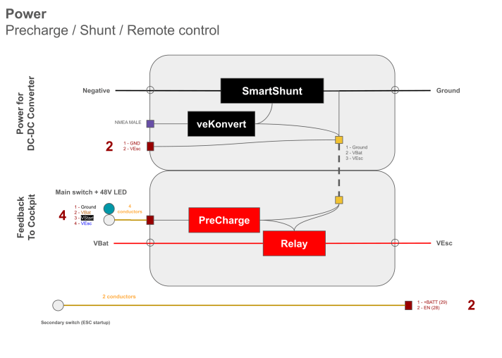
Controls & Communication
Low voltage distribution
What’s next?
We now know how all parts and components are going to work together. Let’s make it real and get the boat ready!


