The concept
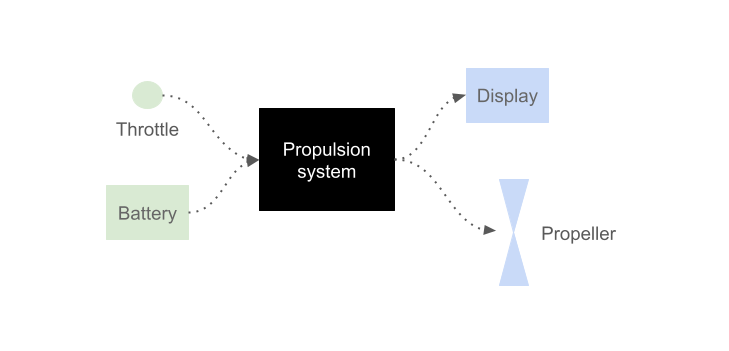
The concept is quite simple. Seen as a black box (see above), the propulsion system receives electrical power from the battery and turns the propeller. Add some control with the throttle and some output to a display and yet we have a system that can do its job.
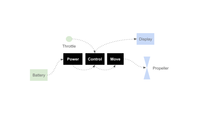
Let’s open the box. We have power flowing in, we control this power, and it generates mechanical movement (i.e. the propeller turns.)
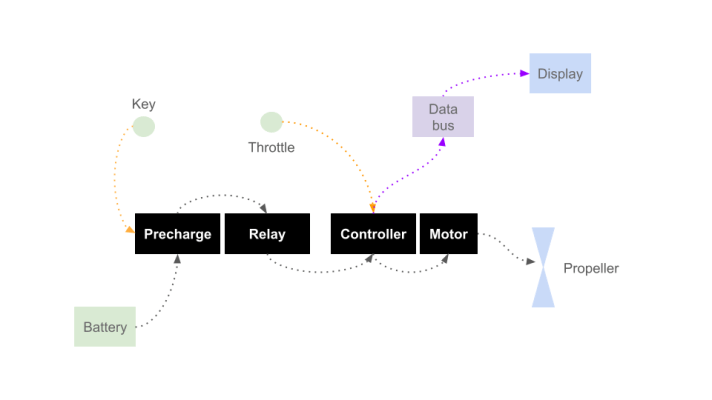
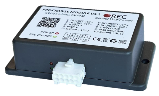
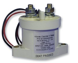
Actually, we need to add a key that switches the power on and off. High voltages and loads with large capacitors need to be switched on in a controlled way : that is the role of the precharge unit. When the key is turned on, it lets the voltage ramp up, over a few seconds, in a controlled way before activating the main relay.
On the output side, the motor controller uses a data bus to communicate with the rest of world (rest of the boat). This data bus will allow the display to get data from the motor controller.
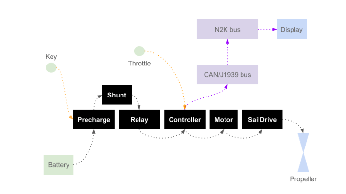
Let’s dive a bit deeper, again. On the power input side, we can add a shunt to monitor the power flowing into the controller and motor. A shunt is just a very low and calibrated resistance, by measuring the voltage drop around the shunt, the flowing current (Amps) can be deduced.
On the mechanical side, between the motor and the propeller resides the saildrive leg. It receives the mechanical input from the motor (vertical rotation), provides some speed reduction, and turns the propeller (horizontal rotation).
In the automotive (and machinery) industry, CAN/J1939 is the standard way of communicating for controllers. “Controllers” is a generic term for “Engine Control Units” (ECU, in the internal combustion engine world) and for “Electronic Speed Controller” (ESC, in the electric motor world). Although the language is the same in both “worlds”, the most common vocabulary is largely focused on internal combustion engines (e.g. data like: fuel rate, oil temperature, etc.)
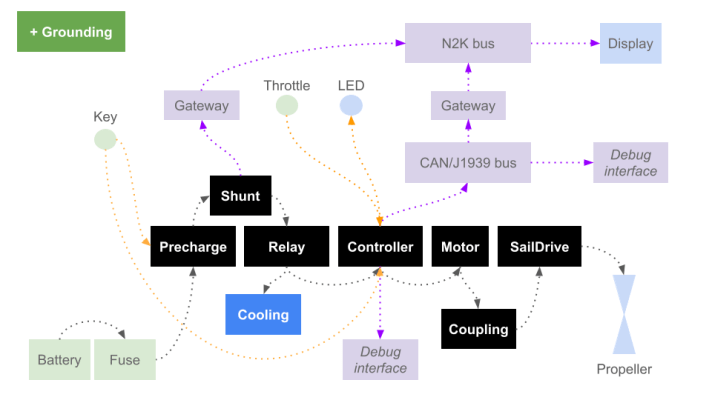
Here is a mostly complete picture now.
In the marine industry, the equivalent bus for communication is NMEA2000 (N2K). It was specified after CAN/J1939 ; while the vocabulary used by both is different, the physical layers (the bus electrical specifications) are the same. Let’s say both talk through the same lips and mouth, but one speaks English and the other one speaks French.
To get data flowing from CAN/J1939 to N2K, we need a translator. This translator is called a gateway: it bridges the two networks and translates messages in both directions. The controller can now send data (motor RPM, motor temp, controller temp, running hours, …) to the display. CAN/J1939 is also used by marine engines manufacturers, which means that finding a CAN/J1939 to N2K gateway should not be too difficult.
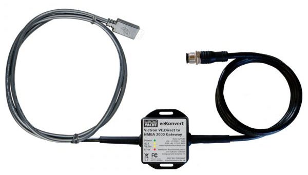
The shunt also needs a translator (another gateway) in order to transmit its data (battery voltage, controller voltage, current, power, etc.) to the display.
For safety reasons, a fuse needs to be installed between the battery and the main relay.
It’s best to have 2 positions on the starter key: first we start the main relay, second we start the motor controller. It’s also reasonable to have a LED in the cockpit to provide some feedback about the state of the power-train.
Between the motor and the saildrive, it is best practice to have a coupling of some sort, in order to bind both components. This is where we have to be creative. No manufacturer does that.
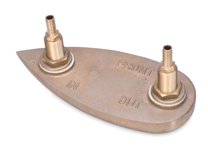
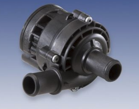
Last mandatory items include: a cooling system for the controller & motor and proper grounding & shielding (to protect against electro-corrosion and electro-magnetic interferences). Sensitive wires are shielded (wrapped in a copper foil), all shieldings are connected together (without making loops!) and connected to the main ground (EP, see below).
As a bonus, it’s always a good idea to have debug ports. Let’s add the basic ones: one USB connection to the motor controller (in case both WIFI and Bluetooth fail), one free plug to connect to the internal CAN/J1939 bus.
What is grounding on a boat?!
On a boat (even more on an electric boat), you have a few things that are usually mixed up, but are different things:
- The Equipotential Plane (aka “grounding”)
- Cable shield
- Negative conductor of the 12V circuit
- Negative conductor of the 48V circuit
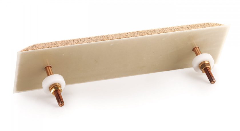
The EP/Grounding is a bunch of components (motor body, saildrive, inverter body, etc.) that are put together at the same electrical potential, and connected to the sea itself. On a boat this avoids having galvanic corrosion happening. I suppose it is also a way for accidental electrical leaks (shortcuts) to escape to the sea, protecting people. Ground loops must be avoided.
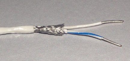
Cable shield is used on sensitive wires (CAN and N2K bus wires, throttle wires, motor encoder wires). A cable shield is not a current-carrying conductor. Its job is to:
- intercept electromagnetic interference (EMI),
- provide a path for high-frequency noise,
- reduce emissions from noisy cables (e.g. motor phase cables),
- protect sensitive signals (CAN, encoder, sensor signals, etc.).
=> For the shield to work well, it needs to be connected to a stable reference (EP).
Both negative conductors on the 12V and 48V systems and not connected to the EP, and should not be connected together, if possible. Keeping the two circuits distinct means:
- electrical noise from the propulsion system will not reach the 12 V electronics
- faults can not propagate easily between systems
Both negative conductors must not be connected to the EP as it:
- improves safety
- reduces galvanic corrosion
- minimizes stray current corrosion
Selected components for this project
Motor
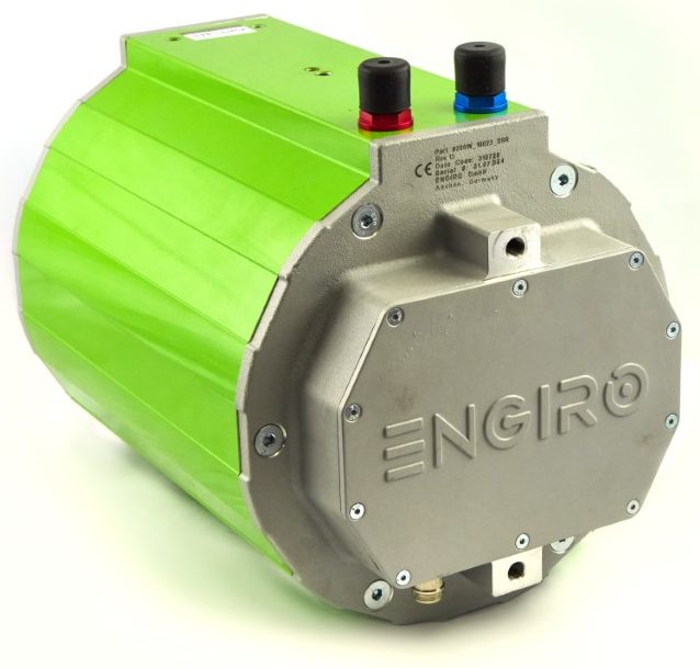
ENGIRO 205W 04013 SHE
- 48 to 200 V
- 12 kW (continuous), up to 20 kW (30s)
- Speed compatible with off-the-shelf saildrives
- High efficiency at the working speed
- Integrated water cooling
- Integrated COS/SIN encoder
The ENGIRO 205W 04013 has been selected in its “SHE” variant (internal/female spline adapter) to reduce the space of the coupling between the motor and the saildrive.
Saildrive
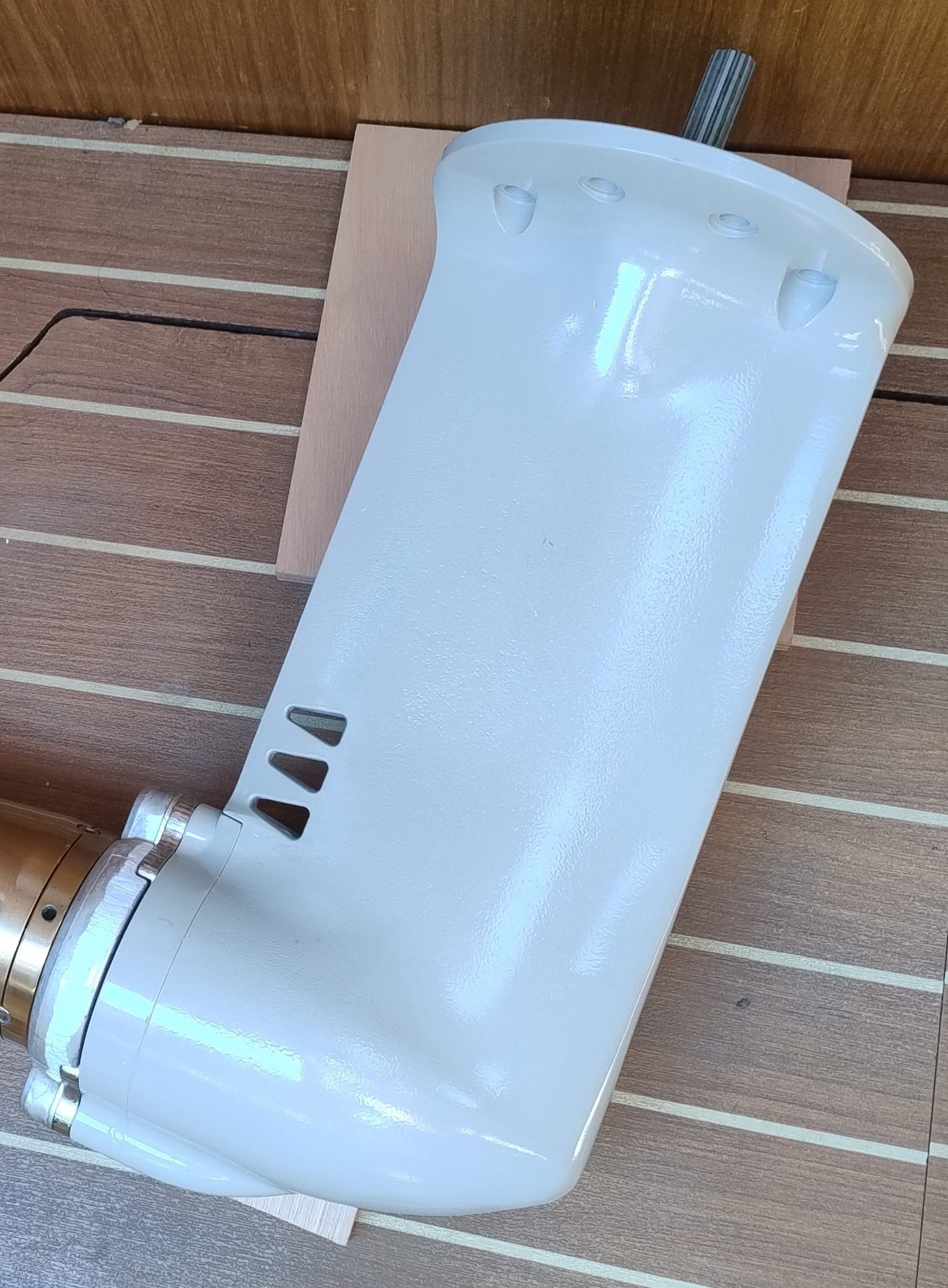
(part #796420-02912)
This is the part between the motor and the propeller, sitting below the hull, in the water.
- It takes care of reducing the motor speed (2.13:1 ratio)
- It offers a standard spline for the propeller
- It keeps the water out…
- … and the oil inside
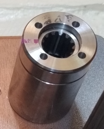
The selected saildrive leg (Yanmar SD25) comes with a torque limiter, placed on top of the input shaft. This is where the mechanical coupling with the motor is happening.
We have no specifications on this torque limiter. However, we know that Yanmar associates this saildrive unit to those diesel engines:
- 1GM10 6.6 kW (9 hp) 3600 rpm ≈ 20–22 N·m
- 2YM15 10.3 kW (14 hp) 3600 rpm ≈ 38–42 N·m
- 3YM20 15.3 kW (21 hp) 3600 rpm ≈ 58–62 N·m
- 3YM30AE 21.3 kW (29 hp) 3200 rpm ≈ 90–95 N·m
It is safe to assume that those engines have a max torque (at the crankshaft) around 100 N.m. The maximum torque for the Engiro motor is 94 N.m, so we should not overpass the limits of the limiter.
Note that we only use the lower part of the SD25 saildrive assembly. The top part has the gearbox (Forward/Reverse) for diesel engines – which is not needed here.
Motor Controller
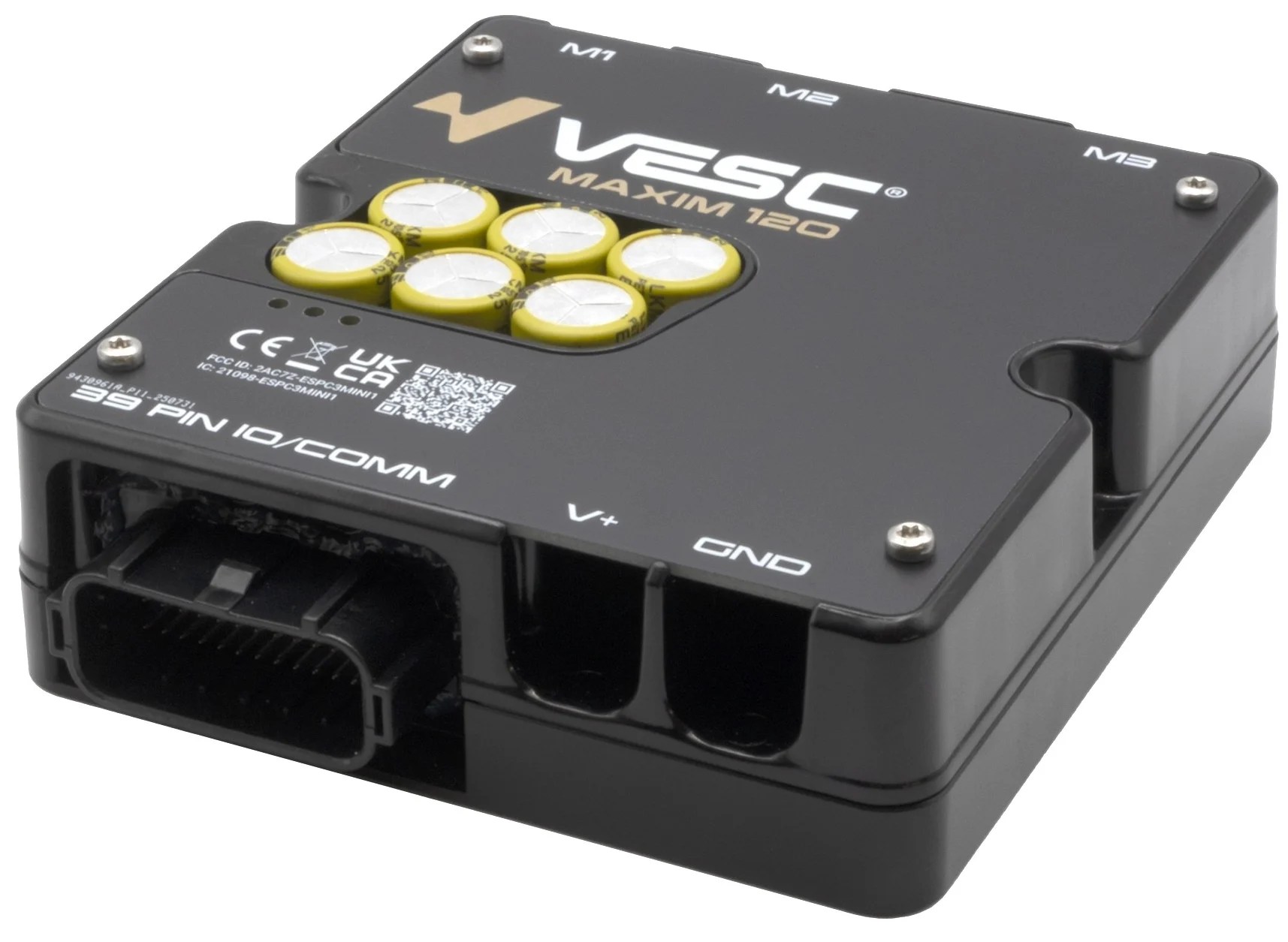
This motor controller (VESC Maxim 120 from VescLabs) has been selected because it is a good match for the Engiro motor, but also because it features an open source firmware and the VESC community is very active.
Shunts and gateways
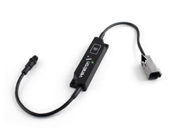
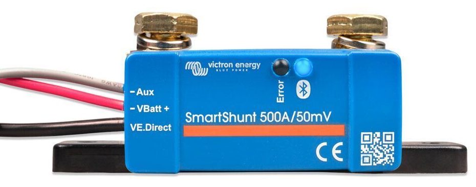
This shunt has a Bluetooth interface and also a VE.Direct port. The veKonvert connects to this VE.Direct port and transfers the data to the N2K bus.
Precharge and Relay
Cooling system
Propeller
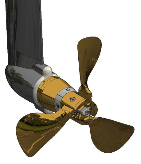
16.5″ x 13″
For now, we are not planning to do regeneration (producing electricity while sailing). Note that this is a personal choice, not a technical limitation of the motor or controller. This Engiro motor is designed to be used as a generator and the controller also support regenerative breaking, including battery overcharge protection.
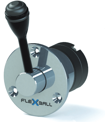
Throttle
Connectors and wires
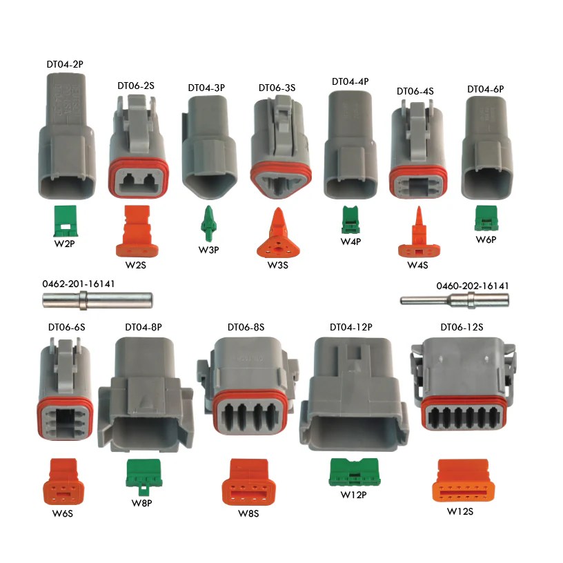
There will be a lot of connectors to be used, for this we choose to use the automotive industry standard: Deutsch DT. It features easy assembly/disassembly, has good contacts, is waterproof and is suitable for signal ware and light power wires (obviously, not for the phase wires 🙂
Battery to Relay and Shunt (high current cables): 2 x 70 mm² (1 m long)
Relay and Shunt to VESC: 2 x 50 mm² (0.5 m long) (max wire size for the terminals)
VESC to motor phases: 3 x 50 mm² (0.30 m long)
Throttle extension cable: 5 wires + shield
All other small wires (12V, USB, CAN, etc): tinned copper with silicon cover
CAN bus and N2K bus
The CAN/J1939 bus and the N2K bus can use the same physical layer (but are 2 different busses, don’t mix them!) We decided to use standard, off the shelf, NMEA2000 hardware (tee-connectors, terminators plugs and wires) for the CAN bus (and the N2K bus obviously) – because they are waterproof and easy to found.
Note that most boats already have an N2K bus (for the navigation instruments). This N2K bus would be fully compatible with it ; but for redundancy sake, we will keep this N2K bus distinct from the navigation bus.
What’s next?
Now that we have all parts, we have to put all components together, design and build the missing parts and make all components work together!


One thought on “Designing an electric saildrive (part #1)”